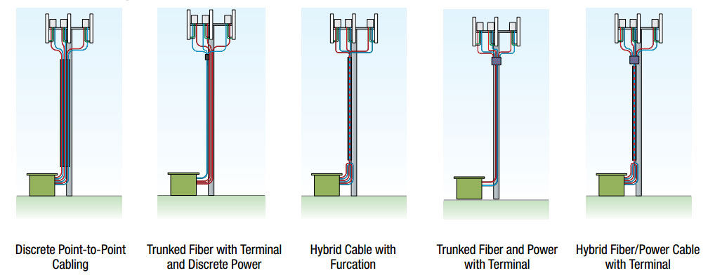
While a number of different system designs have been deployed, FTTA cabling architectures generally consist of a smaller base band unit (BBU) at the bottom of the tower and multiple fiber-fed remote radio units (RRUs) at the top of the tower. Fiber cables replace coaxial feeders running up the tower in order to support advanced technologies such as LTE/4G, which often call for antennas to be multiple in multiple out (MIMO), requiring two or more feeds per antenna to operate.
FTTA design continues to evolve. For example, point-to-point cabling was the early standard for fiber-fed architectures. However, new forward-looking designs incorporate multi-fiber cables for future capability. Hybrid fiber/power cables are gaining traction with some carriers due to the decreased number of tower attachment points. Pre-terminated fiber assemblies have been the norm, but OEMs and mobile operators are exploring more flexible cut-to-fit solutions for the future. Field-mounted fiber optic connectors, for example, allow fiber cables to be cut to length and terminated onsite, eliminating the need to stock varying cable lengths and devise slack storage methods on the tower. Field-mount connectors also reduce installation delays caused by not having the proper fiber cable length on hand at the site.