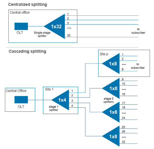
Splitter-based FTTx architectures are a compromise between cost and the flexibility of running fiber to every subscriber location. Instead of running fiber from the central office/ headend to every home like in a P2P arrangement, which is extremely expensive, splitter-based architectures run a single fiber from the headend/central office out to a central distribution point in the network, and via an optical splitter/combiner from that point individual fibers are run to each subscriber location (hence the description “point to multi-point”). This is the physical layer architecture defined in the ITU PON and IEEE PON standards. As shown in Figure 1A, feeder fibers are run to a cabinet near the neighborhood to be served.
Each feeder fiber terminates on a 1×32 optical splitter in the cabinet, which can in turn connect to up to 32 distribution fibers. Typically, the cabinet also provides for managing the fiber cables, splicing the individual fibers and for terminating the distribution fibers on the splitter ports through an interconnect panel. The interconnect panel gives an operator flexibility in activation of the system and utilization of central office/ headend equipment. If an interconnection function is not desired, then the distribution fibers can be directly spliced to the splitter’s output fibers. Each distribution fiber is then run from the cabinet to a drop pedestal location, and through a drop fiber to a subscriber location to serve a single customer. The architecture provides a splitter port and a dedicated fiber for every subscriber location in the serving area.
Alternatively, instead of a centralized splitting implementation (as shown in Figure 1A), multiple smaller splitters, 1:4 and 1:8, for example, can be distributed within the plant (hence the name “distributed split” – Figure 1B). This reduces the requirements for the splitter cabinet, but it also eliminates the original benefits of the splitter-based approach – removes the dedicated fibers from each subscriber back to a centralized point, eliminates the advantage of having all the interconnections at a single point, and increases the network complexity without the benefit of reducing fiber count.
Splitter Based Architecture (Centralized and Distributed Split
| Centralized Splitting (One time Spliting) | |
| Advantages | Disadvantages |
| Stardard based | Costly entry point cabinet required |
| cost savings over a P2P architecture | tape splicing adds labor intensive cost and compexity |
| centralized cabinet for management of cables, splicing and terminating | taper splicing requires detailed record keeping separate mapping and increases design time and cost |
| interconnection panel gives operator flexibility | higher fiber count cables required exiting the cabinet |
| a splitter port and dedicated fiber for ever subscriber | requires mid-span entry technique for larger count fibers for cable access, increased time due to management of remaining cables |
| Distributed Splitting (Cascading Splitting) | |
| Advantages | Disadvantages |
| flexiblity in split ratios in serving area | removes the dedicated fibers from each subscriber back to a centralized point |
| reduces splitter cabinet requirements | eliminates the advantage of having all the interconnections at the point |
| increases network complexity without the benefit of reducing overall fiber count | |

FTTx DISTRIBUTION ARCHITECTURES