IEEE defines 40G and 100G Ethernet in two different standards, respectively are IEEE 802.3ba and IEEE 802.3bm.
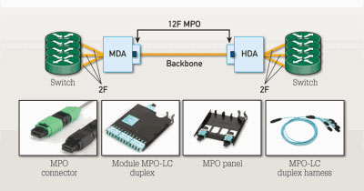
1. IEEE 802.3ba defines both data rates (40GBE and 100GBE) simultaneously. While the singlemode versions operate on two fibers using an LC-Duplex connector, the multimode versions for both speeds are based on multiple (four or ten) data streams of 10 Gbit/s Ethernet in full duplex operation. This requires utilizing eight fibers (40GBASE-SR4) or 20 fibers (100GBASE-SR10) terminated in the multifiber connector MPO.
2. IEEE 802.3bm was published in March 2015 and defines the second generation of 100 GbE using four full-duplex data streams of 25 Gbit/s. This results in using eight fibers terminated in the multifiber connector MPO.
| Channel length | ||||||
| 40GBASE-SR4 | 100GBASE-SR10 | 100GBASE-SR4 | 40GBASE-LR4 | 100GBASE-LR4 | 100GBASE-ER4 | |
| OM3, 50/125 µm | 100 m | 100 m | 70 m | N/A | N/A | N/A |
| OM4, 50/125 µm | 150 m | 150 m | 100 m | N/A | N/A | N/A |
| OM5, 50/125 µm | 150 m | 150 m | 100 m | N/A | N/A | N/A |
| OS1/OS2 9/12 µm | N/A | N/A | N/A | 10 km | 10 km | 40 km |
Channel power budgets for Ethernet applications In addition to the link length definitions, the power budget definition for cabling systems is another critical parameter to monitor when deploying FO applications. The following table outlines the cabling system power budget for the above-mentioned Ethernet applications.
| Network application | Maximum channel insertion loss (dB) | ||
| Fiber Mode | Multimode | Singlemode | |
| Wavelengths | 850 nm | 1300 nm | 1310 nm |
| IEEE 802-3: 10BASE-FL | 12.5 (6.8)** | – | – |
| IEEE 802-3: 1000BASE-SX | 2.6 (3.56)** | – | – |
| IEEE 802-3: 1000BASE-LX | – | 2.35 | 4.56 |
| ISO/IEC 8802-3: 100BASE-FX | 11.0 (6.0) | – | |
| IEEE 802.3: 10GBASE-LX4 | 2 | 6.2 | |
| IEEE 802.3: 10GBASE-SR/SW | 1.60 (62.5)/1.80 (OM2 50)/2.60 (OM3) | – | – |
| IEEE 802.3: 10GBASE-LR/LW | – | – | 6.2 |
| IEEE 802.3: 40GBASE-LR4 | – | – | 6.7 |
| IEEE 802.3: 100GBASE-LR4 | – | – | 6.3 |
| IEEE 802.3: 100GBASE-ER4 | – | – | 18 |
| IEEE 802.3: 40GBASE-SR4 | 1.9 (100m OM3)/1.5 (150m OM4)* | – | – |
| IEEE 802.3: 100GBASE-SR10 | 1.9 (100m OM3)/1.5 (150m OM4)* | –– | |
| IEEE 802.3: 100GBASE-SR4 | 1.9 (70m OM3)/1.9 (100m OM4) | – | – |
* While all listed applications allocate 1.5 dB insertion loss for splices and connections within a cabling channel, 40 and 100 GBE on OM4 requires a lower insertion loss of 1 dB for all splices and connections in a channel, requiring an engineered link using a FO cabling system with highest performing connector technology.
** Values shown are for 62.5/125 μm. Values in parentheses represent 50/125 μm.