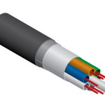
ADSS cables. All-Dielectric Self Supporting cables. The All-Dielectric Self Supporting (ADSS) cable is a completely non-metallic structure in which the tensile load bearing elements are integral within the circular design of the cable – usually in the form of aramid yarns or stranded glass reinfroced plastic rods.
The structure of ADSS Cable
- Typically a loose tube cable design
- Designs are application specific
The Applications of the ADSS Cable
– Cable supports itself
- No external support or messenger wire – Uses new and existing right away
- Distribution or Transmission Lines – Designed to specific weather conditions
- NESC Light, Medium or Heavy Load
The Advantages about the ADSS Cable
- All-dielectric construction
- Eliminates bonding & grounding
- Live power line installation
- Lower costs
Key Specifications for ADSS Cable
- Maximum span distance between poles, Longer spans require more cable strength
- Installation sag: typically 1.5%. Less sag requires stronger cables
- Line voltage: Distribution: Use HDPE jacket span / Transmission: Evaluate line voltage/spacing compatibility, HDPE or track resistant jacket
- Maximum weather loading (wind, ice, safety factors, etc): Higher winds or thicker ice requires stronger cables / Can use location to determine loading per NESC.
- Fiber count: Higher counts (>72) increase the cable diameter: Larger cable diameters have more weight & carry more weather loading
- No of fibers per tube
- Maximum sag restrictions: Any clearance considerations / Restrictions may require a stronger cable
Key Information Needed for ADSS Cable Quotation
- Fiber Count
- Maximum Span Distance
- Weather Loading: NESC Light, Medium, Heavy or Other
- Line Voltage (kV) if transmission lines are used.
– System voltage worksheet required for > 69kV
– Needed to consider dry band arcing and corona resistance
Key Information Needed: Assumptions can be made if not specified
- Jacket Configuration (1 or 2): 1 likely will be assumed
- Initial Installation Sag? 1.5% is typical
Additional information to consider
- Number of Fibers per Tube: 12f/t recommended for distribution spans up to 144 fibers, 4f/t recommended > 144 fibers
- Buffer tube preference for closure routing: Polypropylene < 144, PBT > 144
- Elevation changes?
- Vertical or horizontal sag limitations/clearance
- Pollution level – important in high voltage applications
- Structure type & load capability