Proper testing is a critical part of installing, activating and maintaining a PON. While most components are tested during the manufacturing process, they are tested again after splicing and installation of splitters and access terminals. Field testing is required to ensure no excess loss or reflectance has been introduced due to micro-bends in installed fiber, poor splices, macro-bends in splice closures or access terminals, or dirty, damaged, or improperly seated connectors. If not detected and corrected, excess loss or reflectance often results in poor network performance. Performance may initially seem acceptable, but over time, transmission errors may begin to increase long before the need for any maintenance activity would normally be expected.
Tests commonly used to verify optical links include the following:
• Connector inspection
• Insertion loss test
• Optical return loss test
• Optical time domain reflectometry (OTDR)
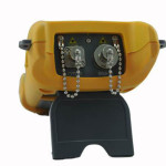
Connector inspection and cleaning during installation and maintenance are among the most effective methods for ensuring an optical network will deliver expected performance. Connector inspection is typically performed using an optical microscope. To prevent accidental eye damage when inspecting fibers potentially carrying live traffic, a video microscope images the connector end-face and displays the magnified image on a handheld display. Dirt, debris, or damage are easily detected. Images may be captured before and after cleaning, then compared for any variation. Connector contamination and damage are the most common causes of poor optical network performance, according to a recent study by NTT-Advanced Technology2.
An insertion loss test measures the end-to-end loss of the installed link by injecting light with a known power level and wavelength at one end, and measuring the received power level output from the other end. The measured difference between the transmitted and received power levels indicates the optical loss through the network. Insertion loss is considered acceptable when the measured loss level is lower than the budgeted loss level.
An optical return loss test injects light with known wavelength and power level into one end and measures the power level returned to that same end. The difference between the injected power level and the measured return level is the return loss. Return loss is considered acceptable when it is higher than the budgeted return loss target. A low return loss value (below 35 dB) is often an indication of one or more sources of excess reflection in the network under test, typically due to dirty or damaged connectors or a fiber break.
Since optical network loss is wavelength-dependent, insertion and return loss testing is typically performed using wavelengths at or near those which will be used during network operation. In the case of FTTx PONs, downstream wavelengths of 1490 nm and 1550 nm may be used, while 1310 nm is used in the upstream direction. Consequently, insertion and return loss testing at 1310 nm, 1490 nm, and 1550 nm may be required. In practice, testing is often performed only at 1310 nm and 1550 nm, reasonably expecting loss and return loss at 1490 nm to be between the levels measured at 1310 nm and 1550 nm.
If the loss and return loss measured at each wavelength are within the levels budgeted for the link, the optical network may be considered ready for activation. However, in many cases, the network operator requires the network to be more fully documented using an optical time domain reflectometer (OTDR).
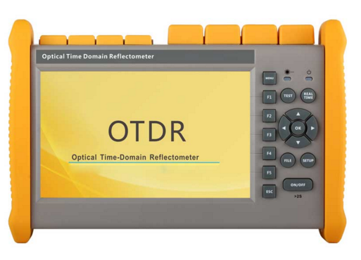
An OTDR scans a fiber from one end to measure the length, loss and optical return loss of an optical network. It also locates and measures reflective and non-reflective events in the network due to splices, connectors, micro- or macro-bends, splitters or faults. Operating like a radar, an OTDR injects narrow pulses of light into the fiber-under-test. As each pulse travels down the fiber, imperfections in the fiber scatter some of the light, with some of this Rayleigh-scattered light being guided back up the fiber.
Optical pulses and backscatter experience some loss as they traverse a mated connector pair, mostly due to imperfect alignment between the two connectors. By measuring the difference between backscatter levels before and after the connection, the OTDR is able to measure the loss across each connection.
A Fresnel reflection is generated whenever the pulse encounters a mismatch in the index-of-refraction, usually at a mated connector. An air gap at a poorly mated connector or an open connector end will generate a strong reflection. This reflected energy is also guided back up the fiber. (Note: The ends of APC connectors are angled to ensure that light is reflected off the end-face at such an angle that it is not captured and guided back up the fiber.)
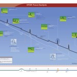
The OTDR measures the level of returned backscatter and reflections vs. time. Since the speed of light through the optical fiber is known, the OTDR is able to convert time-of-flight into distance, creating a trace which plots changes in backscattered and reflected light levels vs. fiber length. Losses due to connectors or macro-bends appear as abrupt changes in the backscatter signal level. Reflections due to connectors, air gaps and open ends appear as spikes in the OTDR trace, as shown in Fig. 2.
End-to-end loss is measured by comparing backscatter level at the beginning of the fiber to backscatter level at the end of the fiber. Reflectance levels are determined by comparing the backscatter level just before a connector to its reflective spike level. Optical return loss can be computed by summing end-to-end backscatter and reflection levels and comparing them to the transmitted pulse power level.
For more accurate connector or end-to-end loss measurements, OTDR traces from opposite ends of a point-to-point network are often averaged using PC-based trace analysis software. Note: Insertion and return loss tests each provide a single numeric value which can be compared to network-specific limits to determine if the optical plant is within acceptable performance values. However, when unacceptable or marginal values are found, insertion or return loss tests cannot locate the source of the problem. An OTDR also measures loss and return loss, but can additionally locate the sources of excess loss and reflections, reporting the distance to high loss or highly reflective events.