As data centers, artificial intelligence, and high-speed networks increasingly demand higher bandwidth and energy efficiency, co-packaged optics (CPO) systems are emerging as a key architecture for next-generation optical interconnects. To address the core challenges of heat dissipation, maintainability, and standardized integration within CPO systems, the ELSFP solution has been developed.
What is ELSFP?
ELSFP stands for External Laser Small Form-factor Pluggable. It is a pluggable module for external laser sources that complies with the OIF-ELSFP-01.0 agreement (published by the Optical Internetworking Forum). Its primary use is in CPO systems, where it separates the laser from the optical engine (OE) and packages it independently as a pluggable module. This enables hot-swappable replacement of the laser source, efficient heat dissipation, and flexible upgrades.
The core interface for the physical connection and electro-optical conversion between the ELSFP module and the system motherboard is the ELSFP connector. This standardized, blind-mate interface, also conforming to the same OIF agreement, is specifically designed to reliably establish and disconnect high-speed optical and electrical paths.
ELSFP Connector Features
1. Host-Side and Module-Side: A Precision Mated Connector Pair
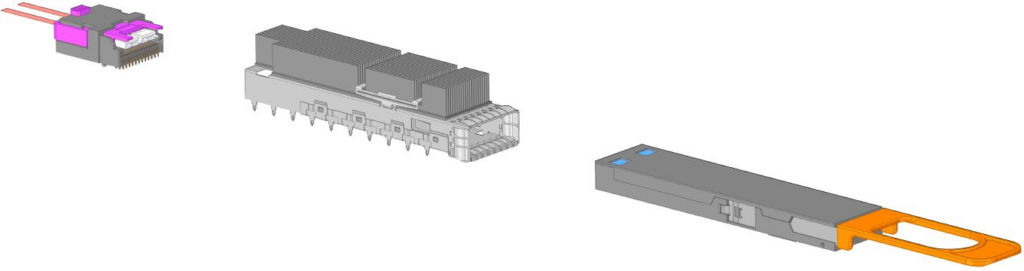
The host-side connector is fixed onto the CPO switch PCB and includes both electrical and optical interfaces. The module-side connector is integrated into the pluggable laser module and automatically aligns with the host connector upon insertion. It supports both “single-sided” and “back-to-back” layouts to accommodate high-density chassis designs.
Operation: When the module is inserted into the cage on the front panel, the module-side connector, guided by mechanical features, blindly mates with the host-side connector, establishing the optical and electrical links in a single action. This separation of the laser source is key to enabling hot-swap capability, facilitating maintenance, and achieving standardization.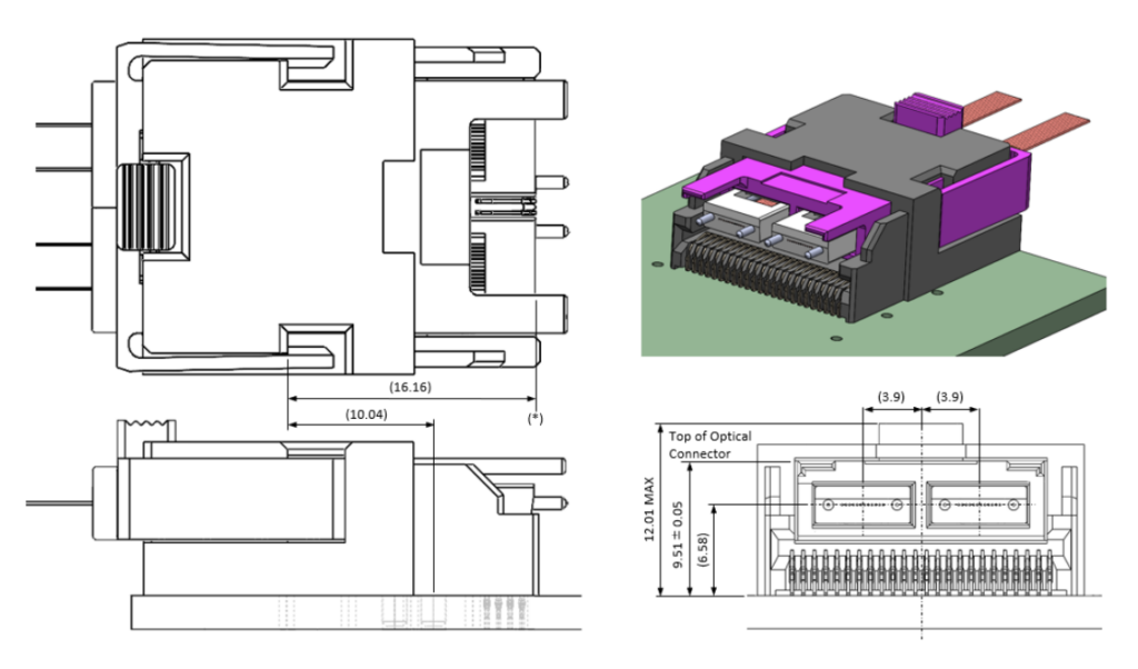
Host-Side Connector
Connection Diagram
2. Blind-Mate Optical Connection
It utilizes MT ferrule-based multi-fiber arrays (supporting 12/24/36 fibers), enabling single blind-mating action with dual MT ferrules. It features a self-aligning structure that ensures precise alignment of fiber end-faces upon mating, preventing damage.
3. Low Insertion Loss
ELSFP connectors ensure low insertion loss through precision fiber optic termini and advanced alignment mechanisms during mating. This characteristic is critical for high-speed data transmission, making them exceptionally suitable for networks requiring high data rates.
4. Safety and Reliability
The blind-mate design ensures eye safety during handling, a crucial aspect for high-power optical applications. It also incorporates robust keying mechanisms to prevent accidental mismating, thereby enhancing system reliability.