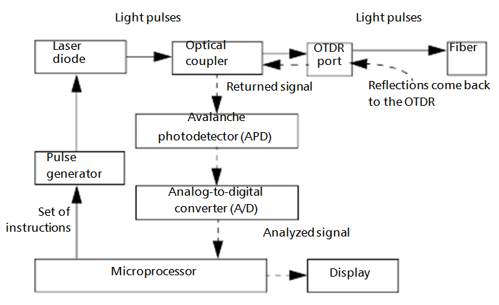
An OTDR sends short pulses of light into a fiber. Light scattering occurs in the fiber due to discontinuities such as connectors, splices, bends, and faults. The OTDR then detects and analyzes the backscattered signals. The signal strength is measured for specific intervals of time and is used to characterize events.
The OTDR calculates distances as follows:
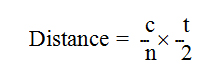
where
c = speed of light in a vacuum (2.998 x 10⁸ m/s)
t = time delay from the launch of the pulse to the reception of the pulse
n = index of refraction of the fiber under test (as specified by the manufacturer)
An OTDR uses the effects of Rayleigh scattering and Fresnel reflection to measure the fiber’s condition, but the Fresnel reflection is tens of thousands of times greater in power level than the backscatter.
Rayleigh scattering occurs when a pulse travels down the fiber and small variations in the material, such as variations and discontinuities in the index of refraction, cause light to be scattered in all directions. However, the phenomenon of small amounts of light being reflected directly back toward the transmitter is called backscattering.
Fresnel reflections occur when the light traveling down the fiber encounters abrupt changes in material density that may occur at connections or breaks where an air gap exists. A very large quantity of light is reflected, as compared with the Rayleigh scattering. The strength of the reflection depends on the degree of change in the index of refraction.
When the full trace is displayed, each point represents an average of many sampling points. You will have to zoom to see each point.