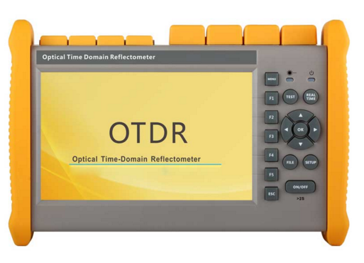
The TLOT-730 OTDR is used to identify cable length and cable fault point or loss events of a fiber optic cable or link. This is mandatory during the installation/fiber acceptance test processes and also during troubleshooting tasks. This application note will provide the beginners with details concerning typical measurements of optical fibers for PON (passive optical networks) and P2P (point-to-point) networks.
1. How an OTDR Works
The optical time-domain reflectometer (OTDR) is an instrument that uses the inherent backscattering properties of an optical fiber to detect faults and categorize its condition. The OTDR sends high power pulses of laser light down the fiber and captures the light that is reflected back (much like a radar system). Correlation is determined between the reflected information and physical locations along the fiber by measuring the timing and power levels of the return pulses. The instrument will display a “trace” that shows the optical power versus the distance. Attenuation of the fiber is displayed as the slope of the trace. Interruptions such as splices, connectors, bends, breaks or flaws in the fiber appear as transitions or “events” that represent their nature and location.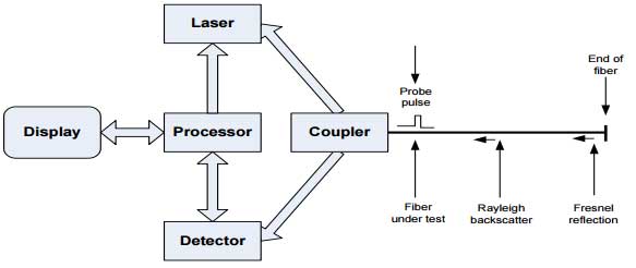
2. Troubleshooting using the OTDR
The TLOT730 OTDR can be used to find the location(s) of fiber damage, while in use or after installation. Fiber is usually found cut or compromised due to a third party rerouting the fiber. Properly documented installations record the installed fiber length, and if there is a reflection before the value, location of the fiber damage are likely identified.
When fiber is cut the resulting reflection is very high and easy to identify. This is typically the location of the cut fiber for a P2P network since there are no splitters or alternate paths for the light to travel. Other reflections could be possible “ghosts” which will be covered later in this application note.
If a technician is troubleshooting a PON system there could be many reflections from an optical network terminal (ONT). This can occur if the measurements are being made from the input of a splitter. Frequently, technicians will not measure from the active splitter because they would have to disconnect the service from all subscribers connected to that splitter. Instead, the technician will often test from the ONT to identify where the fiber is damaged. If the PON is live, the technician should use a TLOT-730F at 1625nm. This allows the technician to measure the fiber cable without disrupting the other subscribers on the network.
Since the TLOT-730 OTDR is using an out-of-band wavelength at 1625nm, and the TLOT-730 is equipped with a filter that only passes 1625nm and blocks all PON wavelengths, the ODTR will not be affected. The PON will also not be affected by the 1625nm wavelength, and network communication will continue functioning for the other subscribers. If the technician knows there is no network traffic, testing can be done with a TLOT-720 at either 1310nm or 1550nm from any point in the circuit.
The technician can also use the visual fault locator (VFL) that is integrated into the TLOT-730. The fiber connector is inserted into the VFL port of the TLOT-730 and the technician can visually identify/locate a possible loss location whether it is a faulty splice or a cut/broken/pinched fiber. The TLOT-730 OTDR also has an integrated stabilized laser source and optical power meter. These can be used to measure the insertion loss of a fiber link or fiber component. One TLOT-730 OTDR is designated as the source and the other TLOT-730 OTDR is the power meter. Individual Greenlee Mini fiberTOOLS™ sources or power meters can be used in tandem with the TLOT-730 power meter and sources.
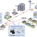
3. Typical PON Configuration
1) The technician will likely see the patch panel, splitter, and/or any fault that may be present when
probing from the ONT.
2) The technician will see up to 32 ONT’s after the splitter when probing from the CO and/or any
fault that may be present.
4. Typical Point-to-Point Configuration
In a point-to-point (P2P) configuration the entire length of the fiber will be measured.
5. Key OTDR Settings
The technician can use the TLOT-730 OTDR in automatic mode. This is a single button operation and allows amateur technicians to troubleshoot and probe fiber networks. The TLOT-730 OTDR will automatically select the appropriate distance range and pulse width at the beginning of the measurement. The TLOT-730 OTDR can also be used in manual mode. This allows the technician to fine-tune the OTDR settings for optimal performance as described below.
The “range” setting needs to be set so that approximately two-thirds of the screen is backscatter signal from the fiber, and the remaining one-third is noise baseline after the last event. Adjusting the pulse width is a situation where the technician needs to weigh the tradeoffs between resolution and dynamic range. A wider pulse width will allow the OTDR to see further and through higher loss devices, but at the expense of signal resolution. A narrower pulse width will have better resolution, but not be able to measure as far of distance or through higher loss devices. A good starting point is to use the default pulse width provided by the OTDR range setting. Increasing the pulse width will increase the deadzones. The event deadzone is the ability of the OTDR to resolve between two reflective (Fresnel) events. The attenuation deadzone is the ability of the ODTR to measure a backscatter event (bad splice) after a reflective event. If the pulse width is too large, then two or more events will merge into what looks like one event. Increasing the pulse width increases the dynamic range of the OTDR, which means that there is more optical power injected into the fiber under test and allows the probe pulse to travel longer distances and through higher loss devices.
A wider pulse width decreases the resolution, but increases the dynamic range and will allow the OTDR to measure longer distances. A shorter pulse width increases the resolution, but decreases the dynamic range but the OTDR will only be able to measure shorter distances. A longer averaging time will improve the signal to noise ratio which will allow the technician to see a more detailed trace with more clearly defined events.
Averaging Time Signal to Noise
Other Causes of Fiber Losses
If fiber is rerouted after installation it may be subjected to macrobends caused by the fiber being moved and subsequently bent. Tie wraps that are overly tight can also cause macrobends. Dirty or damaged connectors and poor splices can cause losses in a fiber link. These types of losses are harder to detect and require the fine-tuning of the TLOT-730 OTDR settings to attain optimum performance.
Troubleshooting Macrobends, Bad Connectors and poor splices
Small events such as macrobends, bad connectors, and poor splices can sometimes be hard to measure and characterize. The TLOT-730 OTDR is capable of finding these events since it has a high dynamic range of up to 38dB (TLOT-730-30). The high dynamic range of the OTDR is attained by the sensitivity of the detector and the algorithms that interpret the data. Some of these events can be less than 0.1dB. With events this small the technician needs to be able to set the range, pulse, width, and averaging parameters for maximum performance.
Fiber link measured at 1550nm. Note that three events are annotated at 1550nm.
This is a typical example of a tie wrap causing a loss at 1550nm of 0.39dB, but very little loss at 1310nm. Macrobends are more problematic at 1550nm due to the minimum bend radius of the
fiber being exceeded.
Trace Viewer for Analysis and Documentation
The TLOT-730 trace viewer software allows the technician to upload the saved files from the TLOT-730 to a personal computer for trace evaluation. Compliance reports can also be generated using the standardized GR-196 SOR file system. All pertinent data including a time stamp and measurement conditions are recorded. Compliance reports can be exported as a PDF copy. Event analysis is sometimes problematic and false events can be annotated with some events being missed. It is suggested that the technician uses the default analysis settings. The event threshold settings can be adjusted to make the annotation more or less sensitive. However, if the thresholds are set too low then random noise might be interpreted as an event.
The “Total Fiber Information Table” summarizes the entire fiber link including a time stamp.
Summary
• The TLOT-730 OTDR can be used to locate catastrophic events such as a cut fiber or to find subtle loss events like macrobends and bad connectors.
• The trace viewer allows the technician to document and produce professional reports of installed fiber links and for use during later troubleshooting.
• The user can locate faults using the TLOT-730 OTDR in the fully automatic mode with only minimum training. With experience the technician can become proficient at troubleshooting difficult faults.
• As the technician gains more confidence with the TLOT-730 OTDR, they will learn the basic principle of pulse width versus resolution and dynamic range.