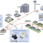
On a data transmission network, one of the main cause for insertion loss on a fiber link is macro bending. This is commonly caused by tight installation or handling. As Fiber-to-the-Home (FTTH) networks lead to a significant increase of fiber installation in the last mile, even G657 fiber are used. the space constraints become increasingly stringent. This is driving the need for distributions hubs and network cabinets to be as small as possible while also increasing fiber density.
Additionally, fiber is being pushed into buildings and closer to the building and residential area to carry optical bandwidth to the business users and home users, All of these aspects have raised the significance of testing link robustness versus macro bends.
As the performance of an optical system is directly related to its wavelengths of transmission, it is mandatory to verify that no additional loss is generated by macro bends by comparing the loss characteristics at different wavelengths.
Macro Bending and OTDR Testing
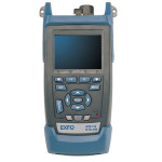
OTDRs are the ideal tools for detecting and locating bends in a fiber link. As macrobend is sensitive to wavelength, most of the operators are testing fiber links with an OTDR, using two wavelengths. The historical wavelengths are 1310 nm and 1550 nm. But the best measurements to analyze macro bending should be taken between 1310 nm and 1625 nm, or between 1550 nm and 1625 nm, which are relevant wavelengths for DWDM testing.
By measuring the same fiber, which includes splices and connectors, using those two wavelengths, of the following information can be provided:
– total insertion loss of the link
– total optical return loss
– loss of any event (splice, connector)
– reflectance of any event (splice, connector, etc.)
– potential macro bends
For a given event (splice or connector), if there is no macro bend, the loss measurement shall be about the same at any wavelength. If there is a large difference (>0.2 dB) between the two wavelengths, this is due to macro bend.
The most modern OTDR, such as the Tarluz OTDR, now offers this comparison automatically and as a standard with the conventional OTDR capabilities. With dedicated information it allows the technician to immediately identify (according to defined thresholds) and locate the macro bends along the fiber link.
Now that OTDR technology has moved into the 1625 nm wavelength area of the spectrum, the same analysis of bending effects must occur.